-
Homebrew Subframe Connectors
by Paul Campbell
Big thanks to
John Pyle and Chris Neighbors for all their contributions!
Note: I
suggest you read ALL of this article (parts I and II) before
you begin. This will help you prepare better and get you
thinking of how the final product will look. If you have any
questions feel free to email me.
Introduction
In the grand tradition of hot rodding, Mustangers often
become mesmerized by the many flashy go-fast goodies the
strong aftermarket tempts us with. Intakes, exhaust, cams,
gears, and/or heads are usually the first things we seek in
our quest to outgun the local heroes. After all, it is power
that makes the performance world go round, right? Well that
is partly true. The fact is, without the ability to transfer
that power to the pavement in an efficient and orderly
manner, all you have is a very cool sounding chick chaser
that is likely to get embarrassed by some of the local rice
burners at a stop light. Even if it is not that bad, you can
still be cheating much of the car's true ability through
inadequate chassis setup.
The Fox chassis is at best designed to only take the abuse
of a stock motored Mustang. It is a flimsy unibody design
with poor weight distribution among other flaws. Even a stock
powered Mustang (or any unibody car for that matter) will
benefit from attempts to counter the twisting force placed on
the chassis as it accelerates. The power used to wrap up the
car can be regained by focusing on minimizing as much flex as
possible. Top of the list is the installation of subframe
connectors to tie in the front and rear subframes, creating
somewhat of a full frame car. Best of all, if you have some
decent fabrication skills, access to a welder, and a free
day, you can build your own for a very meager price. I have
about $15 and 8 hours in mine. There is still some welding to
be done, but they are very functional.
Also, I should note that the second thing every
Mustang owner should consider is the strengthening of the
torque box area. This is where the lower control arm attaches
to the body and is very weak. The torque boxes often will rip
off the car when slicks are run at the track. At minimum, the
sheetmetal will distort and fatigue from abuse, ripping as
illustrated here. I
look at these two areas (subframes and torque boxes) as a
system where each are tied into one another. Thus, some
forethought must be taken as to how the rear of the
connectors attach to the torque box...more on that later.
Options, options....
- If you have browsed through a few different
aftermarket companies' catalogs, you may have noticed
there are several different design approaches to
subframe connectors. There are round ones, square
ones, some bolt on, some weld on, some require
cutting the floorpan, and there are various lengths.
So which is best? Good question that is hard to
answer. The ideal setup is an in-floor connector that
completely replaces the stock subframes. This
requires a complete gutting of the car and a lot of
cutting but since you weld the entire length of the
connector to the body, it is the strongest without
question. Next is something like Wolfe Racecraft
offers where the floorpan is cut but the connector
runs only from the stock connector to the torque box.
They also offer additional bracing to allow the
installation of a cage that fully ties in to the
subframes. (Go here for a good pic). Anothor
option that I highly recommend you consider is the
installation of seat mount brackets such as the ones
found on the Kenny Brown Super Subs. There are
at least two versions I have come up with. If Kenny
Brown's are copied, they must be done before the
connectors are welded on. I will return to this
subject later when we get to that point. Then we come
to the shape debate. In my opinion, the verdict is
still out on whether square or round is stronger in
this application. Theoretically speaking, round may
be better at transfering the twisting force, but in
reality, they both work. I did mine with square
tubing, but you are obviously more than welcome to do
yours as you please. One benefit of square tubing is
that it can be attached much easier. You be the
judge. One thing is for sure:
-
- WELD THEM ON!! DO NOT BOLT!!!
-
Enough of the talk! Let's
get down to business...
Some things you will need, and some things that would be
nice to have:
Need:
Tubing - I used 1.5" x 2" x .120" wall
mild steel tubing. It is possible to use 1" x
2" but unless you have severe ground clearance
problems I would go with the larger. It will take
about four feet per side (add about 16" per side
for full length connectors).
OPTIONAL: about 1.5' of 2" x 2" tubing for
seatmount brackets, depending on version. (highly
recommended!)
4 - M10-1.50 nuts and flat washers for bolting on
seatmount brackets.
3/16" or 1/8" plate - put on each side of
connector as doublers to allow for greater stability
and to cap off the ends.
MIG Welder
Paint
Hand held electric grinder
Jackstands or ramps - If you are doing this alone
(not recommended) you need a couple of extra
jackstands or jacks (bottle jacks are best) to hold
them up against the car while you fit and weld.
Floor jack
Bandsaw, or cutoff saw, or hand held cutoff tool (die
grinder with discs), or even hacksaw if you are
desperate - You need something to cut the tubing.
Soapstone or marker - to mark the pieces for cutting.
Tape measure
And of course, eye protection!
Nice to have:
A helper - This is really a need but you could make
do.
3M weld-through coating. Makes a zinc coating where
you weld. (Really a need, but I guess you can do
without.)
Air compressor
90 degree die grinder with sanding discs for cleaning
Camera - to show off your creation (I might even put
it here if you do something creative)
The first thing is to get the car up off the ground. If
you are using jackstands, it is imperative you place them
under the rear axle and front A-arms and the car is as level
as possible. This puts the car under a similar load as when
sitting on the ground as all the weight is transferred
through the suspension. Just make sure they are solid at ever
place. Next, get under the car and survey the situation. You
will see that the transmission crossmember is connected to
the front subframes. You want to start the connector
1/4" or so from behind that point unless you are doing
the full length design. Make
note of the locations of brake lines and/or fuel line now. You obviously want to avoid these items
while welding. In the rear, examine your torque boxes.
Make note of all the seams around this area and check them
for tears, bending, or any obvious distortion. If they have
been badly abused, you might consider going ahead and
reinforcing them while you have the car in the air. At least
weld up all the seams if you can't do some reinforcements at
this time. Chris Neighbors and myself are planning a good
writeup on reinforcing this area for the near future. The
rear of the connector will attach to the bottom of the large
flat area in front of the notch for the lower control arm. I
left mine about 3/4" forward to allow the lower plate
that will be fabricated for the reinforcement of the torque
box to be attached a little more solidly.
WARNINGS
Before you do any welding consider how close you are to
the interior of the car. If you care about it at all and want
to forego the winter wonderland effect left by the fire
extinguisher, remove the seats and peel back the carpet where
you weld. Have someone keep an eye out for too much smoke
and/or flames. This is especially true if you weld the seams
on the torque boxes. The metal at this point is thin to say
the least. I left my carpet in for the entire subframe
connector portion, but melted some of the padding when the
front plates were welded at the top. Be safe...peel yours
back.
Also, before doing any welding on a vehicle, you should
disconnect the grounds from all sensitive electronic devices:
battery (to isolate alternator), EEC computer (if
applicable), stereo amplifiers, timing/nitrous control/BTM's,
etc. Welding on a vehicle with the grounds attached may
create a ground fault loop that could send a spike to theses
devices, causing damage and erratic function.
Take the time to clean all the areas
where welding will be done down to the bare metal. You can
use a variety of tools, but I found a 90° die grinder with
sanding discs work very nicely. I would caution against a
stone type grinder as the metal isn't overly thick in most
places you will be cleaning. Better to use something that
will only remove the surface stuff and not the surface too.
When everything is clean, spray the 3M weld-through coating
on all bare surfaces and allow it to dry.
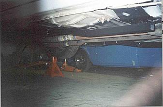
To help you create a plan, here are some
pictures of mine after they were finished:
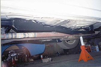
Please, no laughing at the exhaust welds...:)
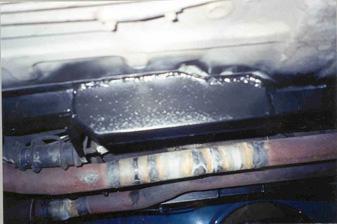
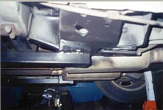
Here are some closeups of the front and back:
So now you should have an idea where to clean
as well as some idea of how the end product will look. By all
means, go ahead and do it 'your way' if you think you have a
good idea. This is just how I did mine and certainly not the
last word in subframe connectors.
Click below for part two:
Part 2