Note: This article is intended to serve as a supplement to the service manuals listed at the end. If used right, it will guide you around some annoying and potentially disasterous situations you might encounter in your rebuild. Just remember: if you are not sure ASK! It could save you a lot of time and money.
T5 Rebuild: The saga
written by Chris Neighbors
The problem:
After many abusive, over-torqued powershifts, the venerable T5 is left a little worse for wear. Couple this with no built in shift fork limits, and the frequency of failure is quite high in any spirited driven vehicle. Or, in some cases, the high-mileage often seen on Mustangs results in worn out friction linings on the blocker rings. (My first (and only, so far!) failure was a delaminated fourth gear blocker. I could upshift, but had to pause a while to downshift, until it went out altogether, at 125,000 miles!) Update: July 2, 1999: Blew input shaft at lunch! Thing sounded like a grenade going off; left with fourth gear only! Now I feel like a real man, LOL!
The solution:
Why, a thorough rebuild, of course! While going through the rebuild, do you and your trans a favor by spending some of the money saved on upgrades: the two most notable are a steel input shaft bearing retainer and a decent aftermarket shifter (or at least do something about the factory rubber isolators, like remove them!). Besides learning how to do a rebuild to get yourself out of trouble, its a great bartering skill when your "friends" blow theirs up!
The sources:
I have purchased parts from both D&D Performance and Hanlon Motorsports. I have received outstanding service from both, and always receive my parts in a timely manner. I have not dealt with National Drivetrain, but have to believe they are on par with their competitors. Personally, I prefer to deal with Hanlon; Linda, Bobs wife, always makes me laugh when I speak with her, and they had the courtesy to call me several months after I placed an order to let me know the Tremec rebuild manuals were in.
Vendor |
Phone |
Fax |
Website |
D&D Performance |
(248) 926-6220 |
||
Hanlon Motorsports |
(610) 469-2695 |
(610) 469-2694 |
|
National Drivetrain |
(800) 507-4327 |
(773) 376-9135 |
Required tools: (well, maybe not all required; some merely desired )
Required chemicals:
The Teardown:
I am going to assume that you have successfully drained and removed the trans from the vehicle; if you havent, shut off the computer and back away slowly! Seriously, it is my contention that if you can remove the trans without hurting yourself or breaking something, you should be able to accomplish the rebuild. If the trans is fairly dirty, do yourself a favor and cart it down to the local car wash for degreasing and pressure washing; nothing bothers me (personally) more than to try to do a rebuild on a grungy component. Well break the trans into seven areas: tailhousing (TH), cover (C), input shaft (IS), overdrive (OD), main shaft (MS), cluster gear (CG), and reverse (R). Before you begin, study the exploded views (in the Helm or Tremec manual) of the entire trans. You might (and should) blow a copy up and keep handy during the rebuild.
Tailhousing:
Remove eight (8) tailhousing to main case fasteners with 15mm wrench/socket. With shifter removed, drive pin through shift block with 3/16" punch. The pin may not fall all the way through; as long as it clears the shift shaft youre fine. Break the sealant bond between the tailhousing and main case by carefully prying with a flat screwdriver; dont try to remove housing, just break it free of the case. Apply slight downward pressure on the shift block, and simultaneously slide block off shift shaft while removing tailhousing from the trans. Once the block is free, continue to pull all the parts off and place on the bench. If the vent didnt come off, remove it from main case and place into the locating feature on tailhousing (normally the sealant keeps it in place).
Cover:
The cover, which also contains the shift forks and shift shaft, is attached with ten (10) fasteners. Remove the neutral indicator switch (top, front, drivers side of trans), being careful not to damage it (I broke one of mine, and found out later it is a Ford only item (Hanlon had a used one, thank goodness ). Try and save yourself some aggravation!). Youll also find an activation pin below the switch; retrieve and secure it. Using your 10mm tools, remove all the fasteners. Two (2) of the fasteners are shoulder bolts; they fit in one place (well, two actually ) only, and align the cover to the main case. Use a screwdriver between the cover and the main case to break the seal (youll find that the cover overlaps the case at the corners; perfect places to pry!). Slide the loose cover towards the passenger side, to clear the reverse mechanism; lift up.
Input shaft:
To gain access to the input shaft, remove the four fasteners that hold the input shaft bearing retainer to the main case with 13mm tools, and remove retainer. Rotating the input shaft, notice the crescent shaped cutout in the blocker-like portion. To remove the shaft, align cutout with cluster gear and pull forward. As you pull the input shaft, look at the interface between it and the mainshaft; there are loose roller bearings inside the input that support the mainshaft. Its OK if they fall out, but pay attention to the bearings and shims that cage the loose bearings and provide clearance between the input and main shafts. Some T5s use a steel spacer (looks like a flat washer) on top of the loose bearings; others do not. Just be aware of this, and reassemble with the same parts stack-up. Remove the thrust bearing, spacer, and blocker from the 3-4 synchro at this time. If you plan to replace the input shaft bearing, remove it using a bearing separator and balancer puller (or shop press).
Overdrive:
I am grouping all components located inside the tailhousing in the overdrive area, even though not all are related. Remove the small plastic oil slinger that is in the end of the cluster gear with pliers, screwdriver, etc. If your trans is equipped with a rubber output shaft seal, align it with the splines and pull off. Depress retaining clip that holds speedo gear in place, and slide gear rearward, off the output. The clip will fall loose, once the speedo gear slides far enough to clear. Remove the snap ring that holds the 5th driven gear onto the mainshaft with external snap ring pliers, and slide gear off. Drive the roll pin out of the 5th gear shift fork with the 9/32" punch. Remove synchro retainer snap ring and retainer from exposed end of cluster gear. Simultaneously slide the shift fork and the 5th synchro off of their respective shafts, making sure not to disassemble synchro just yet (or mark ring to hub orientation and disassemble). Remove brass blocker and 5th drive gear.
Main shaft:
With everything removed from the front and rear, the mainshaft assembly should come right out. Wiggle the front a little to unseat the bearing race at rear of main case, and remove. Lift the front of the shaft slightly and towards passenger side, and pull assembly out, guiding output shaft through bearing race hole. Set the whole assembly aside for now. Well treat it as a separate subassembly, as it contains the bulk of the parts.
If you are "fortunate", and havent blown up third with a missed shift, you will most likely be able to skip the next two steps
Cluster gear:
Stand the main case on its forward face (bellhousing mount face). Using a hammer and chisel, bend over the four fastener lock tabs on the bearing retainer. Remove the four fasteners with the T40 Torx bit, and set fasteners, retainer, and shim aside. To allow removal of the cluster, the rear bearing must be removed (or at least the cage and rollers). Use the bearing separator and balancer puller (or shop press) or two/three jaw puller to remove the bearing (The 94-piece rebuild kit from D&D comes with new bearings, so dont get too concerned if you have to destroy it. Or see "Service parts" below.). Finagle cluster gear out of the main case.
Reverse:
Remove the reverse light switch, located on the driver's side of the main case, with the 7/8" wrench. The Helm and Tremec manuals both require you to remove the reverse gear shift lever pivot pin BEFORE you do anything (well, before you remove gearsets). For the life of me, I have not been able to remove three of three, to date. Dont fret it too much. Remove retaining clip and reverse shift lever (if it wont come out now, remove it after the shift rail and reverse idler are removed). Drive roll pin through the reverse idler gear shaft (This can be fun! The shaft will try to rotate as you drive the pin through. If you manage without getting blood blisters, congratulate yourself!). Push the shaft rearward, out the back of the main case; grab reverse idler gear and o-ring when they fall off the shaft. Unhook rail spring, and pull rail out the back of the main case. Note: Sometime in 1993, Borg-Warner changed to a torsion spring (from an extension spring) to force shift rail forward. I cant recall off-hand how or where it attaches; if you find a unit with the torsion, just make note of it and proceed
Congratulations! You successfully completed the teardown, and should have quite a pile of parts around you!
Clean up on aisle 9!
One of my pet peeves is casting flash; the other is sharp edges left after machining. You should have noticed during disassembly that nearly every edge of the T5 is sharp; some nearly razor. I take a flat file and break all the sharp edges on all major aluminum parts. While this isnt required, it only takes about five minutes, and if you can avoid a cut or three (and then getting cleaning fluid in it (especially carb cleaner! Yeow!) it is well worth the time (in my opinion). If you blew third gear up, the large magnet in the bottom of the main case will have many pieces of shrapnel stuck to it. Carefully pick these away, and wash out main case. Dont worry about removing magnet; its epoxied in (I fought the first one for about ten minutes, then realized this!). Blow the case out with compressed air, or let air dry. Repeat as required on all the other parts, save for the main shaft (leave it assembled, for time being). If you plan on replacing the tailhousing bushing, now is a good time to remove it. Remove old seal, and either drive bushing out or deform it with a screw driver, or cut with cold chisel, and pull out (the bushing has a seam in it; if you can find it and pry on one side, they usually "split" and come out without getting overly aggressive). There is a drain groove in the tailhousing; the perfect place to get a chisel/screwdriver under the bushing to start deformation. If you damage the bore while removing the bushing, touch up the damage with a small file and 180-220 grit sandpaper.
Main shaft:
The mainshaft has the greatest number of components than any other single sub-assembly. For this reason, it is advisable to clear the area of all other parts while working on it. I like to stack the parts in order and correct orientation upon removal. Starting from the front of the main shaft, mark the 3/4 synchro hub and outer ring to insure proper reassembly. Remove the ring, being careful to not let the synchro inserts and springs fly off. The synchro hub may slip off, or it may need some coaxing with a two/three jaw puller. When I rebuilt my last unit, I could not get a hold of the hub with my small two-jaw pullers. I didnt want to set up the shop press, so I placed a piece of ¼" thick aluminum plate on the concrete floor, and repeatedly dropped the main shaft assembly on the plate until the hub came off. It took about eight to ten blows, and the plate protected the end of the shaft from damage. Remove the blocker, 3rd driven gear, caged bearing, and spacer. With the retaining ring pliers, expand the retaining ring and slide off of the mainshaft. Slide off the spacer, 2nd driven gear, caged bearing, and spacer. Using thin screwdriver(s), remove spiral retaining ring, then remove thrust washer, inner and outer cones, and blocker. Mark orientation of 1-2 synchro ring to hub. Remove ring, inserts, and springs. From the rear of the MS, remove the retaining ring and slide off 5th driven gear, and main shaft bearing and race. Slide 1st gear, caged bearing, sleeve, blocker, and inner and outer cones off of the MS. Be careful during removal, as there is a spring and ball or pin detent under the sleeve; dont let it fall out and get away from you.
Inspect all components (per Tremec manual) as you clean and install them in the proper order. Lube the caged bearings with trans fluid before installing into appropriate gears. When installing first gear sleeve, note the notch in the I.D. that engages the detent (pin or ball) on the main shaft. Synchro assemblies can be trying; I usually have to do them two or three times to get them together without springs flying and inserts falling out. Just be patient and persistent, and youll get them in place (but make sure marks are lined up!). Refer to the Helm or Tremec manuals for assembly details (There arent many! 3-4 synchro has "winged" inserts; the springs that hold the inserts in place should be installed in opposite directions on each side (actually, if you install both clockwise, they will be opposite)). The tabs or ears on the outer rings of the 1-2 synchro should be oriented so that they fall into the notches in the 1st and 2nd gears; if not, the parts wont stack up properly.
And now for a little assembly!
Cluster gear front bearing race:
If you are replacing the cluster gear, and desire to change the front race (if its not galled, pitted, or damaged, it may be reused ), then do so now with nothing else in the main case. Refer to the Helm manual for procedure and set-up to correctly replace the race. I placed my race in the freezer for a couple of hours prior to installation. I pulled the race out, installed o-ring, applied Loc-tite 271, and pressed race into main case, using proper supports. Not difficult, but some care must be exercised.
Reverse:
Install the shift lever and clip. Roughly locate the shift rail block in position. Slide the rail shaft through the rear of the main case and into the rail block; install spring and continue pushing the rail forward, inserting into the pilot bore in the front of the main case. Locate the reverse idler gear grossly in place, and slide the shaft, from the rear of the case, through the rear pilot far enough to get the idler onto the shaft and located in the forks of the shift rail block. Push the shaft in a little further, then install o-ring. The o-ring keeps the reverse idler from slamming into the shaft boss cast into the main case. Drive the roll pin into the reverse idler shaft, leaving about 3/16" to 1/4" sticking above the top of the shaft. Attach the extension spring to the post in the main case, or install torsion spring.
Cluster gear:
Clean the cluster gear, regardless if new or used. Install the new front bearing using the 1-7/8" O.D. pipe, and either press or drive it on with a sledge, making sure small diameter of bearing is away from the cluster gear. If you dont have a press, heat the bearing in an oven at about 200 degrees for a few minutes prior to installation. Even with no heat, it will go on quite easily if lubed and driven on. Install the cluster into the main case, seating bearing in race. Stand the case on the bellhousing mount face. Install the rear cluster bearing using the same procedure as the front. Measure the thickness of the original shim, record, and install, followed by bearing retainer and fasteners; torque to 11-15 lb-ft. DO NOT BEND TABS UP AT THIS TIME! With the top of the main case towards you, so you can see (and still on bellhousing face), set up dial indicator to read cluster gear endplay and zero out. Pry the cluster gear up with a large screwdriver, and note amount of endplay. The factory endplay range is .001"-.005". If the endplay is not within these specs, install the appropriate shim that will provide proper endplay. Note: I could not achieve proper endplay on one trans I built with the shims I had available. I either achieved slight interference, or .008" endplay. I tried to lap the thicker shim a few thousandths, but failed to reduce the thickness after several minutes I took the shims to work with me the next day, hoping to grind them. No grinder was available. I finally cyanoacrylated (super-glued) the shim centered on a piece of round stock. I placed four equidistant drops of adhesive, set the shim, and let it cure for a couple of minutes. I then chucked the slug in a lathe and turned a few thousandths off. To remove the shim, I simply rapped the shim on the edge of a table, and the adhesive broke free! Once the proper endplay is achieved, torque the fasteners to spec (11-15 lb-ft) and bend lock tabs up to contact one flat on each fastener.
Main shaft:
Insert the main shaft assembly by poking output shaft through hole in rear of main case. Let driven gears rest on cluster gears, and install rear bearing race into bore.
Input shaft:
Look inside the bearing area, and youll see two reliefs: a narrow deep one, and a wide shallow one. The wide, shallow relief should be installed towards the bottom, to allow oil to drain properly from IS bearing. Temporarily install the input shaft bearing race into the input shaft bearing retainer without any shims. Install the shaft into the bearing retainer, and all loose rollers, shim, thrust bearing, and spacer into the counterbore in the end of the input shaft, held in place with Vaseline. Rotate the crescent shaped cutout of the input shaft so that it will clear the cluster gear and install. Install fasteners and torque to 11-20 ft-lb. Stand the trans up on the bellhousing face and supported so you have access to input shaft. Set up the dial indicator to read output shaft endplay and zero. With a block of wood, force the input shaft up, and read the endplay on the dial indicator. Return the trans to horizontal, and remove input shaft bearing retainer. Remove bearing race from inside retainer, and install shim the same thickness as the observed endplay. This will provide .000" endplay (the factory allows plus or minus .002", however). Reinstall bearing race, and apply 1/8" bead of RTV to bearing retainer sealing surface. Install retainer with flat narrow drain back at bottom, apply sealant to fasteners, and torque to spec.
Overdrive:
Notice the step and the lettering on the 5th driven gear; they should be oriented towards the tail of the trans (closest to snap-ring). (I got a call one night from a couple of guys who were rebuilding a unit, and had driven the gear on backwards; took them about an hour to remove it, without a press. They flipped it around, and it slid home!) Install the 5th driven gear on the output shaft, then snap ring, making sure it seats in groove. Install 5th drive gear on the exposed end of the cluster gear with hub towards the front, and blocker mating surface towards rear. Apply thin coat of Vaseline to the inside of the brass blocker and install. Install 5th gear synchro on the cluster gear and shift fork on shift rail. Pay attention to orientation of 5th gear synchro assembly: the taper on the O.D. of the sliding ring should be installed towards the rear of the trans. The shift fork should be installed with the fork offset to the rear, also. Once assembled, align holes in shift fork and shift rail, and drive roll pin into place (about halfway through shaft). Install plastic oil slinger into end of the cluster gear.
Cover:
If you have to replace a damaged shift fork, see the Helm or Tremec manual for parts sequence and procedure. Install new o-ring on shift shaft boss, and a 1/8" bead of RTV on the main case to cover sealing surface (may be best applied to main case). Let it set for a few minutes, then carefully lower cover onto main case while engaging shift forks into grooves in synchro rings. Install cover fasteners and torque to 6-11 lb-ft. Install neutral switch and pin.
Tailhousing:
If you removed the bushing during clean-up, install a new one now. There are a couple of ways to get the bushing in; drive it in with the correct size bushing driver, or put the bushing in the freezer for several hours and hope you can get it in place before it warms up (it might help if you put tailhousing in the oven at around 200 degrees for fifteen minutes or so to expand it ). Lube the bushing with ATF, then drive it in until the end is even the tailhousing chamfer (not the major diameter; the diameter below the seal counterbore). Blow the housing out, as small slivers of aluminum and bushing material will be created during installation. Apply a thin layer of RTV to the shell of the rear seal and drive seal into place with the 3/8" or 1/2" punch; tap with hammer around the circumference of seal to avoid damage. Apply a 1/8" bead of RTV to the main case mounting surface (and around vent) on the tailhousing. Let the RTV cure for a few minutes, then line up over output and shift shafts. Lube the o-ring on the cover with Vaseline or trans fluid. Install spring in shift block and hold in place with Vaseline. Drop detent ball onto detent plate; push shift block over ball (with shifter bushing towards the rear), and align with shift shaft. Simultaneously push tailhousing and shift block forward, making sure shift rail and cluster gear bearing race pilot in their respective bores. Once "home", prep the bolts with sealant, install, and torque to 20-45 lb-ft. Wait to install shifter until the trans is in the car; the easiest way to fill it with fluid is through the shifter hole.
Miscellaneous tidbits:
Speedometer drive gear:
If you have installed gears in your Mustang, you may be the victim of an inaccurate speedometer. Ford used a seven (7) tooth drive gear in the 1983 to 1989 T5s, then switched to an eight (8) tooth drive in 1990 (used through 1995). If you have 3.73s with an eight tooth drive, and the highest driven gear with twenty-three (23) teeth, the speedometer still reads 5% fast. Now is the optimum time to correct the situation, with the transmission apart for service. With the limited number of gears available, the combinations are (number in the table is the driven gear tooth number to be used with left hand gear ratio and drive gear column) :
| Rear end ratio / Speedometer drive | Seven (7) tooth drive |
Eight (8) tooth drive |
3.27 |
18 |
21 |
3.55 |
20 |
23 |
3.73 |
21 |
n/a |
4.10 |
23 |
n/a |
Shifter considerations:
If you dont want to cough up the money for an aftermarket shifter, there are a couple of things that can be done with the stock unit to provide more feedback; both involve removing the rubber bushing in the shifter handle. The cheapest is to braze the holes up, and drill with a "P" drill bit, in the correct locations. Steeda offers stainless steel shifter bushings; they install in place of the rubber units in minutes. While these two modifications improve driver feedback, they do not prevent the shift forks from overshifting inside the trans. Overtravel of the shift forks is the main cause of shift fork failure.
Trans fluid:
Whatever you do, do not use gear oil (e.g. 80W90) in a T5! The lubrication passages are so small on some components that gear oil will not flow readily and lubricate properly. You stand a chance of spalling, galling, or otherwise destroying a trans if pushed to extremes. Use Dexron II, Mercon III, or a synthetic ATF. Some synthetics have friction modifier in them; if you can find one without it, opt for that one (read the back of the container; usually they indicate whether modifier is present or not). If you use a synthetic, I have found (in the handful of friends' cars that run it) that the trans tends to whine a little more than with conventional ATF. If you don't mind the slight amount of noise, the increased service interval is nice (I drive mine 100 miles per day!). The fluid capacity is 5.6 pints (2.8 quarts); just fill up until it runs out of the top fill port (on the passenger side).
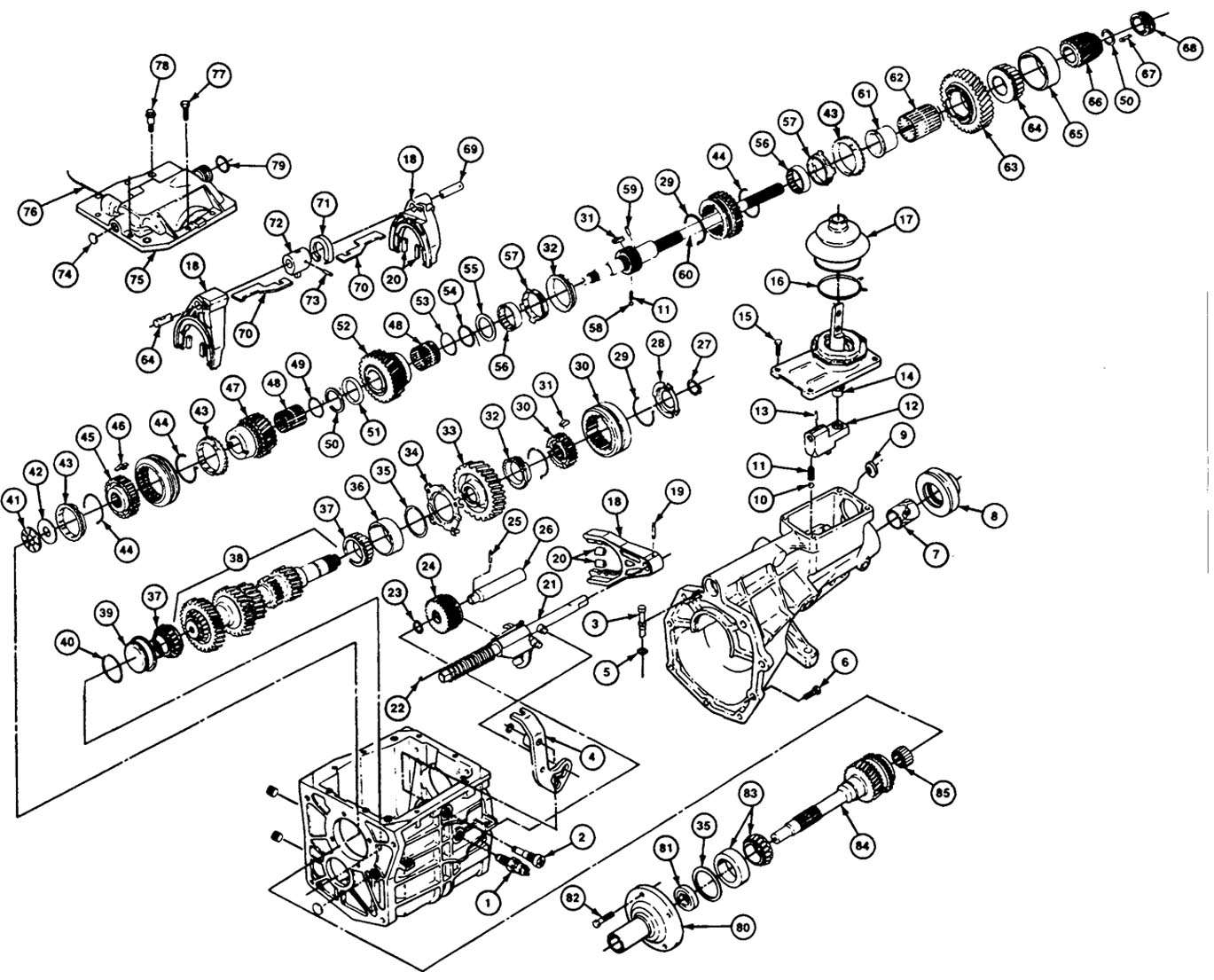
Parts list: (numbers correspond to exploded assembly drawings)
No. |
Description |
No. |
Description |
No. |
Description |
1 |
Switch, back-up lamp | 32 |
Ring, 5th gear blocking | 63 |
Gear, 1st drive |
2 |
Pin, reverse gear shift | 33 |
Gear, 5th drive | 64 |
Bearing, outputshaft rear |
3 |
Vent, case | 34 |
Retainer, cluster bearing | 65 |
Race, output rear bearing |
4 |
Lever, reverse gear shift | 35 |
Shim, cluster endplay | 66 |
Gear, 5th driven |
5 |
O-ring, case vent | 36 |
Race, cluster rear bearing | 67 |
Clip, speedo gear retaining |
6 |
Bolt, tailhousing to case | 37 |
Bearing, cluster rear | 68 |
Gear, speedo drive gear |
7 |
Bushing, tailhousing | 38 |
Gear, cluster | 69 |
Shaft, shift |
8 |
Seal, tailhousing output | 39 |
Cup, cluster front bearing | 70 |
Plate, gear selector |
9 |
Plug, tailhousing shifter | 40 |
O-ring, cup seal | 71 |
Plate, gear interlock |
10 |
Ball, shifter detent | 41 |
Bearing, roller thrust | 72 |
Block, gear selector |
11 |
Spring, shifter detent | 42 |
Shim, thrust bearing | 73 |
Pin, block retaining |
12 |
Block, shift | 43 |
Ring, 3-4 blocker | 74 |
Plug, shift shaft |
13 |
Pin, shift block roll | 44 |
Spring, ¾ synchro insert | 75 |
Cover, trans top |
14 |
Bushing, shifter | 45 |
Hub, 3/4 synchro | 76 |
Pin, reverse switch |
15 |
Bolt, shifter | 46 |
Insert, 3 /4 synchro | 77 |
Bolt, top cover |
16 |
Clamp, shifter boot spring | 47 |
Gear, 3rd driven | 78 |
Bolt, top cover shoulder |
17 |
Boot, shifter | 48 |
Bearing, 3rd caged roller | 79 |
O-ring, tail to cover |
18 |
Fork, 4-5 shift | 49 |
Spacer, 3rd gear bearing | 80 |
Retainer, input bearing |
19 |
Pin, shift fork roll | 50 |
Ring, external retaining | 81 |
Seal, input shaft |
20 |
Insert, shift fork (pad) | 51 |
Shim, 2nd thrust washer | 82 |
Bolt, input bearing retainer |
21 |
Rail, shift | 52 |
Gear, 2nd drive | 83 |
Bearing, input shaft |
22 |
Spring, shift rail block | 53 |
Spacer, 2nd gear bearing | 84 |
Shaft, input |
23 |
O-ring, reverse idler stop | 54 |
Spacer, | 85 |
Bearings, loose roller |
24 |
Gear, reverse idler | 55 |
Shim, 1/2 synchro thrust | 86 |
Ring, 3/4 synchro |
25 |
Pin, reverse idler roll | 56 |
Cone, inner 1/2 gear | 87 |
Ring, 5th gear synchro |
26 |
Shaft, reverse idler | 57 |
Cone, outer 1/2 gear | 88 |
Block, shift rail |
27 |
Ring, external snap | 58 |
Ball, 1/2 synchro detent | 89 |
Fork, 3-4 shift |
28 |
Retainer, 5th gear synchro | 59 |
Pin, 1/2 synchro detent | 90 |
Fork, 1-2 shift |
29 |
Spring, 5th synchro insert | 60 |
Shaft, output (main) | 91 |
Spring, synchro pin detent |
30 |
Hub, 5th gear synchro | 61 |
Sleeve, 1st gear bearing | 92 |
Shim, input shaft endplay |
31 |
Insert, synchro hub | 62 |
Bearing, 1st caged roller | 93 |
Race, input bearing |
Exploded assembly view:
Rebuild kits:
Hanlon refresh kit includes: 8, 20, 32, 43, 79,
Service parts: (if you didnt buy rebuild kits)
Cluster gear bearings:
| Front race: | LM67010-BCE |
| Rear race: | LM67010 |
| Bearings (same): | LM67048 |
Input shaft bearing retainer:
| Bearing: | LM48548 | |
| Race: | LM48510 | |
| Seal: | UCO 159G | NOK |
Main shaft rear bearing:
| Bearing: | 25877A | Timken |
| Race: | 25821 | Timken |
Tailhousing bushing: 02105 Clevite
Rear seal: 7692-S or 7052-AA
References: